The ZR1's LT5 engine has two induction stages consisting of sixteen air intake runners, sixteen fuel injectors and two fuel pumps. The primary eight runners and injectors, operate during both primary and secondary induction, while the secondary runners and injectors come on line only during the secondary induction stage. Other than during engine warm-up, the secondary fuel pump is activated only under high engine loads during the secondary induction stage to meet injector requirements.
To verify pump operation turn the ignition key to "ON" for 5 seconds. The pumps should run for about 2 seconds. With a rag on hand, remove the cap on the Schrader valve, located on the fuel rail above the alternator, and depress the center pin to release pressurized fuel. If fuel does not spray out for at least 1/3 of a second you could have an issue. If you have a fuel pressure gage connect it to the Schrader valve and, again, turn the ignition key to "ON" for 5 seconds. The gage should indicate 45-55 PSI and hold steady. If the system is under pressurized, you might have a fuel pump issue, if the system pressurizes correctly but drops quickly, you might have a leak, a faulty fuel pressure regulator or a 'stuck-on' injector.
To perform a cursory test of the primary injectors, disconnect the Gray or Yellow connector to the ECM. Clip a test lead to the negative terminal of the battery or any suitable grounding spot. With the ignition key turned to "ON", insert the other end of the test lead into the connector provision for each fuel injector one at a time and listen for an audible click.
Here are the applicable locations on the Gray or Yellow connector:
Pin 1 - Injector 1,
Pin 2 - Injector 7,
Pin 3 - Injector 5,
Pin 7 - Injector 2,
Pin 8 - Injector 6,
Pin 12 - Injector 8,
Pin 13 - Injector 4,
Pin 18 - Injector 3.
For additional clarity, see the ECM "A" illustration below.
The LT5 Utilizes 16 Intake Runners and 16 Fuel Injectors
Knowledge Carries a Lot of Torque!The primary and secondary injectors receive the same negative feeds from the ECM. Conversely, the positive feeds are different between the primaries and the secondaries. To test the secondary injectors without having the primaries activate at the same time, it is necessary to remove the 20 AMP "INJ 1" fuse.
To perform a cursory test of the secondary injectors, the process is similar to that of the primaries, except two test leads are attached to the negative terminal of the battery or any suitable grounding spot. Disconnect the Gray or Yellow connector to the ECM and the Brown connector to the ECM. With the ignition key turned to "ON", insert one test lead into the Gray or Yellow connector and one test lead into the Brown connector, in accordance with the chart in the next few paragraphs. Check each secondary injector one at a time and listen for an audible click.
Here are the applicable locations on the two connectors:
BROWN: Pin 16, GRAY or YELLOW: Pin 2 - Injector 7,
BROWN: Pin 16, GRAY or YELLOW: Pin 7 - Injector 2,
BROWN: Pin 17, GRAY or YELLOW: Pin 1 - Injector 1,
BROWN: Pin 17, GRAY or YELLOW: Pin 12 - Injector 8,
BROWN: Pin 21, GRAY or YELLOW: Pin 3 - Injector 5,
BROWN: Pin 21, GRAY or YELLOW: Pin 8 - Injector 6,
BROWN: Pin 22, GRAY or YELLOW: Pin 18 - Injector 3,
BROWN: Pin 22, GRAY or YELLOW: Pin 13 - Injector 4.
For additional clarity, see the ECM "A" and ECM "D" illustrations below.
Check the 16 Injectors Without Removing the Plenum
Knowledge Carries a Lot of Torque!If all 16 injectors pass the basic 'click' test, it might become necessary to remove the plenum to test further in an effort to resolve any driveability issues.
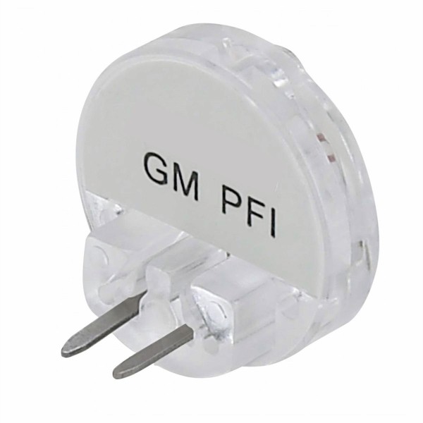
Some of the tools needed will be a long and narrow Torx T-40 socket or power bit for the plenum bolts, a standard Torx T-30 socket for the MAP Sensor and, for the throttle cable and its cover, a Torx T-15 screwdriver and 7mm socket. An example of a T-40 power bit for the plenum bolts is pictured here.
Disconnect the negative terminal of the battery before proceeding. Avoid working on a hot engine. Do not force or over-tighten any bolts or screws that fasten to the aluminum LT5 engine.
Disconnect the Battery Negative Terminal Before Plenum Removal
Knowledge Carries a Lot of Torque!Start by removing the accordion hose between the air filter assembly and the throttle body extension opening to the plenum. A long slot screwdriver or an 8mm socket will undo the two clamps. Then disconnect the electrical plugs to the Manifold Air Temperature sensor (MAT) and the Idle Air Controller (IAC). Disconnect the coolant-air-bleed hose on the passenger side of the engine where it joins the pipe that runs along the plenum.
Remove the throttle cable cover from around the Throttle Position Sensor (TPS) and disconnect the cable or cables from their respective cam or cams. Remove any brackets that hold the cable or cables to the plenum. Unplug the electrical connector to the TPS.
The Manifold Absolute Pressure sensor (MAP) can be detached from the plenum by removing the two T-30 bolts which mount the sensor bracket to the plenum. The vacuum line from the plenum needs to be removed but the electrical connector does not.
The vacuum line from the plenum to the fuel pressure regulator should be removed.
Carefully loosen all twelve Torx T-40 Plenum bolts. To avoid damage to the bolt heads, do not use a worn T-40 socket that slips. Once all 12 bolts are loose, remove them completely.
Gently lift and separate the plenum from the left and right injector housings (a.k.a. lower plenum), by placing one hand on the throttle body extension and the other hand where it is convenient on the rear side of the plenum. There will be some resistance at first but the seal around the plenum gaskets will readily give. Do not attempt to remove the plenum entirely at this point.
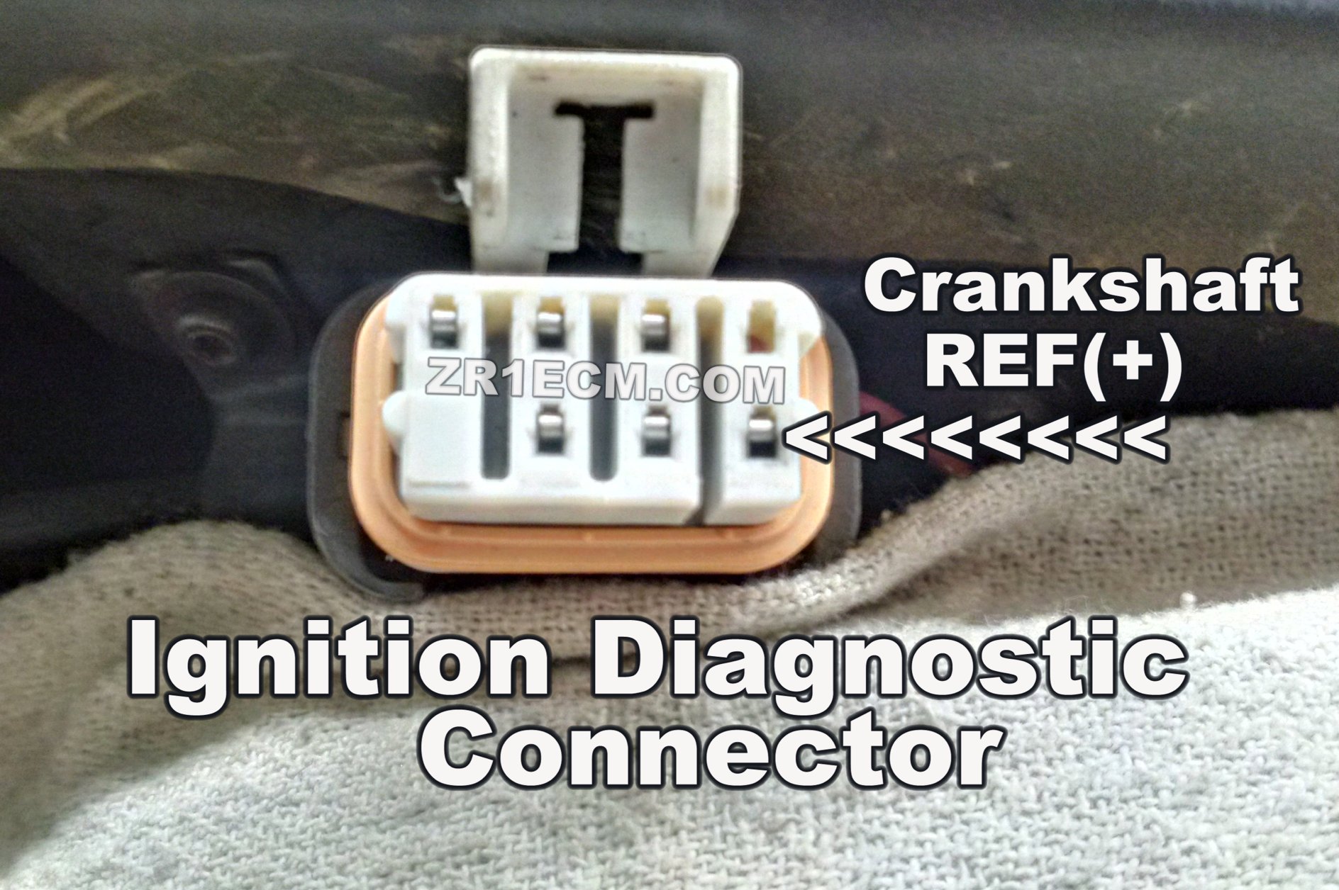
Once the plenum seal is broken, gently lift it near the MAP sensor and completely loosen the 8mm bolt that secures the main electrical connector to the Ignition Module. This bolt remains attached to the connector once it is removed from the ignition module. Unplug the crankshaft sensor connector next to it. Unplug the two connectors that connect the ignition module to the four coils. Along the way, remove any remaining hoses that will prevent the removal of the connectors to the ignition module or the plenum itself.
Once the 4 connectors to the ignition module are unplugged and all the bolts and hoses are disconnected or moved out of the way, it is safe to carefully lift and remove the plenum.
It should be noted that from time to time it is necessary to remove the plenum to service components related to the C4-ZR1's engine. If the left and rear plenum gaskets are in good condition, they can be reused. If the plenum hasn't been removed in some time, it is good engineering practice to replace the gaskets when reattaching the plenum to the top of the engine.
Tag: C4, Corvette, ZR1, LT5, ECM, DIS


