With the plenum removed, it is possible to troubleshoot in circumstances where a diagnostic code has not been produced by the fault. This includes issues with the Crankshaft Sensor, Ignition Module, Ignition Coils, Engine Control Module and Fuel Injectors. This page provides insight when troubleshooting the Engine Control Module.
As outlined on page 2, the LT5 engine utilizes sixteen fuel injectors, one pair for each cylinder. The ECM drives each pair with a negative signal provided by eight MOSFET Power Transistors. The positive signal for the primary injectors is applied anytime the ignition key is turned to "ON", while the positive signal for the secondary injectors is controlled by the ECM through two solid-state relays.
To test the ECM driver circuits, emphasis is placed on the primary injector circuits, however it should be noted that a failure in the secondary injectors or the solid-state relays can disrupt the functionality of the ECM and the primary injectors. The tests presented on this page should be initially performed with all the primary and secondary injectors completely disconnected except for the one primary injector under test, then repeated with its matching secondary connected.
The Crank-Reference-High (+) signal is normally sent by the Ignition Module to the ECM. This signal is based on the raw signal provided to the Ignition Module by the Crankshaft Sensor. A defective Crankshaft Sensor will prevent the Ignition Module and, in due course, the ECM, from receiving a correct crankshaft reference. It is, therefore, good engineering practice to replace this low cost sensor when driveability issues are noticed.
At this point, there are two methods to test the ECM to verify it is sending eight distinct negative signals to each of the eight fuel injector pairs. The first method involves sending a simulated Crank-Reference-High (+) signal to the Purple/White wire running between the ECM and the Ignition Module. The objective of this first method is to invoke a 'cranking-start-up' condition, during which engine RPM is under 400 and the ECM is programmed to activate all primary injectors simultaneously. The second method involves opening the ECM and sending a 5 volt positive signal directly to the Gates of each of the eight Power Transistors, one-at-a-time.
Simulating the Crank Reference High (+) Signal
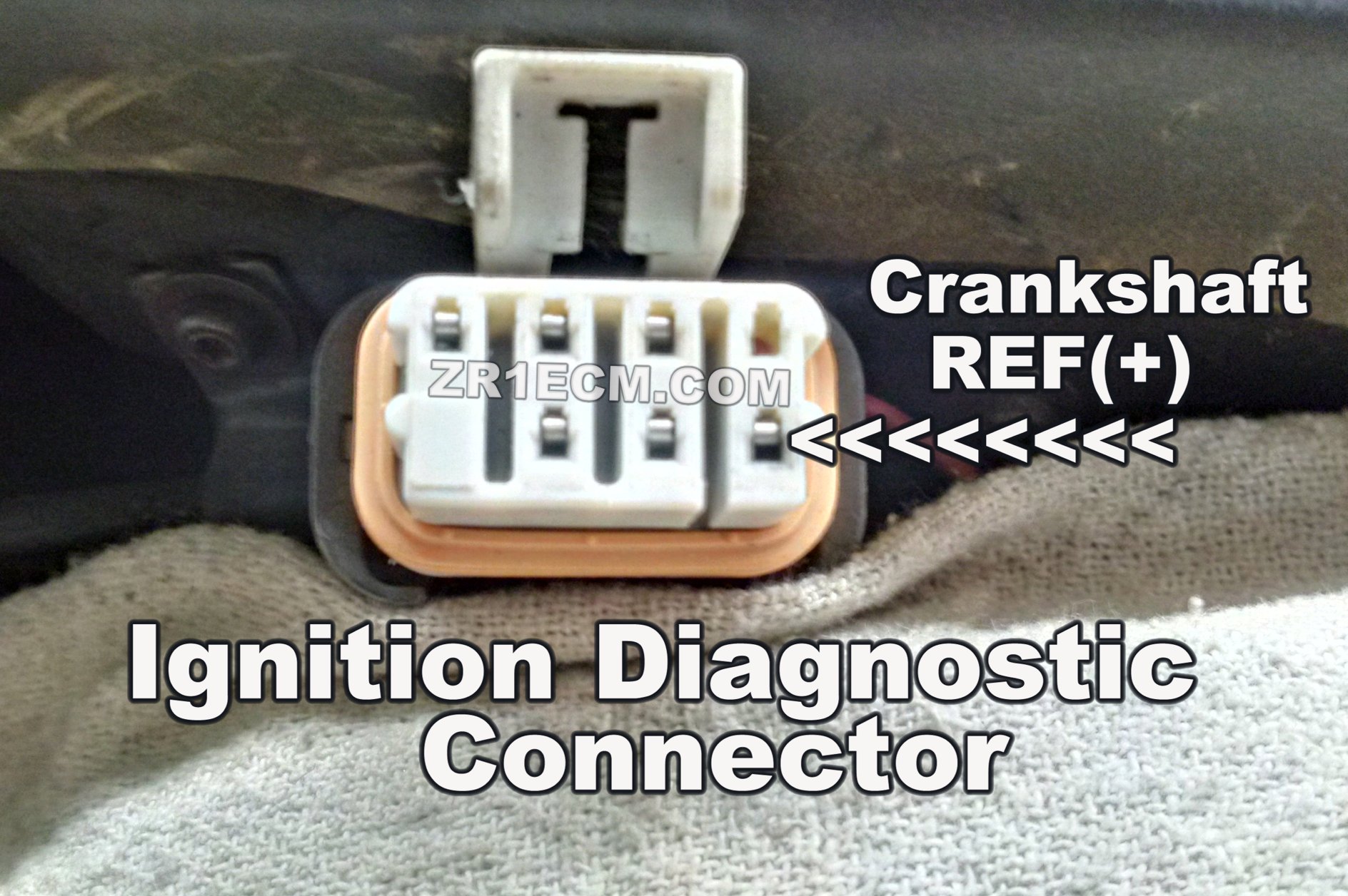
Knowledge Carries a Lot of Torque!A simulated Crank-Reference-High (+) signal can be inserted at "Terminal A" of the Ignition Diagnostic Connector or, while the plenum is removed, at "Terminal F" of the main connector which mates with the Ignition Module. This wire is Purple/White in color. The circuit connects to the ECM at Pin 18 of the Brown connector. For additional clarity, see the "Ignition Diagnostic Connector" image below.
It is possible to spoof a square wave pulse on the Crank-Reference-High (+) circuit without any specialized equipment. Connect the alligator clip from a standard 12VDC test light to the positive terminal of the ZR1's battery and then repeatedly tap the probe end of the test light against the input terminal of the Crank-Reference-High (+) circuit, five to ten times a second.
For more refined testing, a signal generator can be used to simulate the Crank-Reference-High (+) signal. Set the output to pulse a square wave 20 times a second (20Hz) within a 0 - 5VDC range. This equates to 300 crankshaft revolutions per minute.
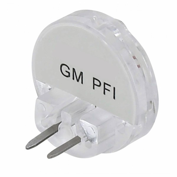
To verify the ECM is sending a negative signal to the eight pairs of injectors, a 'noid' light can be substituted in place of each injector's solenoid, one-at-a-time. A GM specific Port Fuel Injection (PFI) 'noid' light plugs directly to the connectors that would normally attach to LT5's injectors. This approach is recommended in noisy environments or where faulty injectors are suspected. If a 'noid' light is not available, a standard 12VDC test light can be used.
Once the aforementioned is configured, turn the ignition key to "ON". Using a standard 12VDC test light connected to the negative of the battery or a chassis ground, confirm each primary injector connector is receiving 12VDC on its respective Orange/Black wire. The secondary injector connectors are not energized with positive voltage during this testing procedure.
Once a positive voltage is confirmed at the primary connectors, keep the ignition key turned to "ON" and apply a simulated signal to the Crank-Reference-High (+) circuit then listen for the fuel pumps to engage and wait for the primary injector to click or the 'noid' light to blink. If there is a click or a light blink, the ECM is correctly sending a negative signal thru that injector circuit's wiring. Connect that cylinder's matching secondary injector and retest. The results should be the same, that is, the primary injector should click or the 'noid' light should blink. Repeat this process, one-at-a-time and in pairs for all the injectors.
The aforementioned testing process verifies firstly, that the ECM is sending a negative signal to all the injector connectors and secondly, that the secondary injectors and their solid-state relays are not adversely acting upon the ECM's ability to do so.
The ECM is likely faulty if it is unable to provide a negative signal to all eight injector pairs. This could be the result of a defect on the ECM's circuit board trace-layout, requiring a solder reflow process, or it could be the result of a defective component, like an Application Specific Integrated Circuit (ASIC) or a Power Transistor. A method to test these transistors follows.
Testing the Transistors Inside the ECM
Knowledge Carries a Lot of Torque!IMPORTANT NOTE: Some level of electronics knowledge and skill is required to perform exposed-circuit testing of the LT5's Engine Control Module. The testing procedure outlined on this page is limited to verifying that the eight N-MOSFET Power Transistors are in working order. Do not work on the ECM in areas where static electricity is prevalent.
To remove the ECM, disconnect the negative terminal of the battery. Remove the two 10mm nuts holding the ECM to its support bracket. Squeeze the tabs and wiggle out the four electrical connectors attached to the ECM. The ECM can now be removed from the vehicle.
The ECM cover utilizes 8mm bolts. Prior to sliding back the ECM's cover, it is necessary to remove the MEM-CAL cover-plate and the MEM-CAL daughter board. The board is held in place by two press-down tabs, one on each side. Once the bolts and the MEM-CAL board are removed, the ECM can be pulled out of its cover from the connector side.
Place the ECM on a clean well-lit table. Take notice of the eight power transistors and their matching labels on the main circuit board. The board indicates Q1 thru Q8 and each transistor will have a label reading "SDG". The "G" means GATE. Applying 5 VDC to any one "G" pin causes that particular transistor to send a negative signal to the fuel injector pair that it is connected to.
A foot long 22 gage wire can be soldered to the circuit board to provide a 5 volt source, suitable for testing the eight transistors. A convenient spot is available at IC U13 - 23232. The jacket on both ends of this test wire should stripped by about a millimeter. For additional clarity, see the "ECM U13 - 5 VOLTS" image below.
When testing the eight transistors with the ECM circuit boards exposed and connected to the car, it might be easier, especially in the case of transistors Q1 thru Q4, to apply 5 volts from a test wire on the underside of the main board. To prepare for this, it is best to mark, the "G" pins with their matching underside solder points.
Exposed-Circuit-On-Car Testing
Knowledge Carries a Lot of Torque!Before re-connecting the ECM to its four electrical connectors, return the MEM-CAL daughter board to the ECM's main board. The MEM-CAL can only be inserted one way. Be sure to push the board in completely, so the two retaining tabs lock in place.
To perform exposed-circuit testing, reconnect the ECM to the vehicle, while making certain the 5VDC test wire is not coming into contact with anything and that the main circuit board is positioned with the underside of the transistor "G" pins facing up, for easy access. Once this is completed, connect the negative terminal of the battery and turn the ignition key to "ON".
When 5VDC from the test wire is applied to the GATE of each transistor, one-at-a-time, the transistor under test, should send a negative signal to the wiring of its matching injector pair. If this does not occur, the transistor could be failing.
Since the secondary injectors will not receive a positive signal during this testing process, only the primaries will click, or illuminate, if a 'noid' light is used. All eight transistors should be checked at first, with just the primary injectors connected and subsequently with both the primaries and secondaries connected.
The transistor component numbers, indicated by a label on the circuit board, do not directly correlate to the LT5's cylinder or injector numbers. This chart provides a quick look-up.
Transistor Q1: Cylinder/Injector #6
Transistor Q2: Cylinder/Injector #5
Transistor Q3: Cylinder/Injector #7
Transistor Q4: Cylinder/Injector #2
Transistor Q5: Cylinder/Injector #1
Transistor Q6: Cylinder/Injector #8
Transistor Q7: Cylinder/Injector #4
Transistor Q8: Cylinder/Injector #3
The eight Power Transistors used in the LT5 ECM are generic and available on-line. They are MOSFET N-Channel Power Transistors, in a TO-220 package.
Tag: C4, Corvette, ZR1, LT5, ECM, DIS